Pedal-powered walking beast
Course:
ENGS 146
Computer-Aided
Mechanical Design
Date:
Spring 2016
Team Size:
5
Key Responsibilities:
Drivetrain Subassembly
Transmission Design & Manufacture
Skills:
Finite Element Analysis
CNC Shopbot
Mechanical Design
CHALLENGE: To design and build a pedal-powered walking machine that can accomodate any human rider between 5'6" and 6'1" and compete in a jousting competition.
MEET ATHENA: OUR PEDAL-POWERED WALKING GODDESS
MODELED VERSION OF ATHENA IN SOLIDWORKS
KEY SUBASSEMBLY DESIGNS:
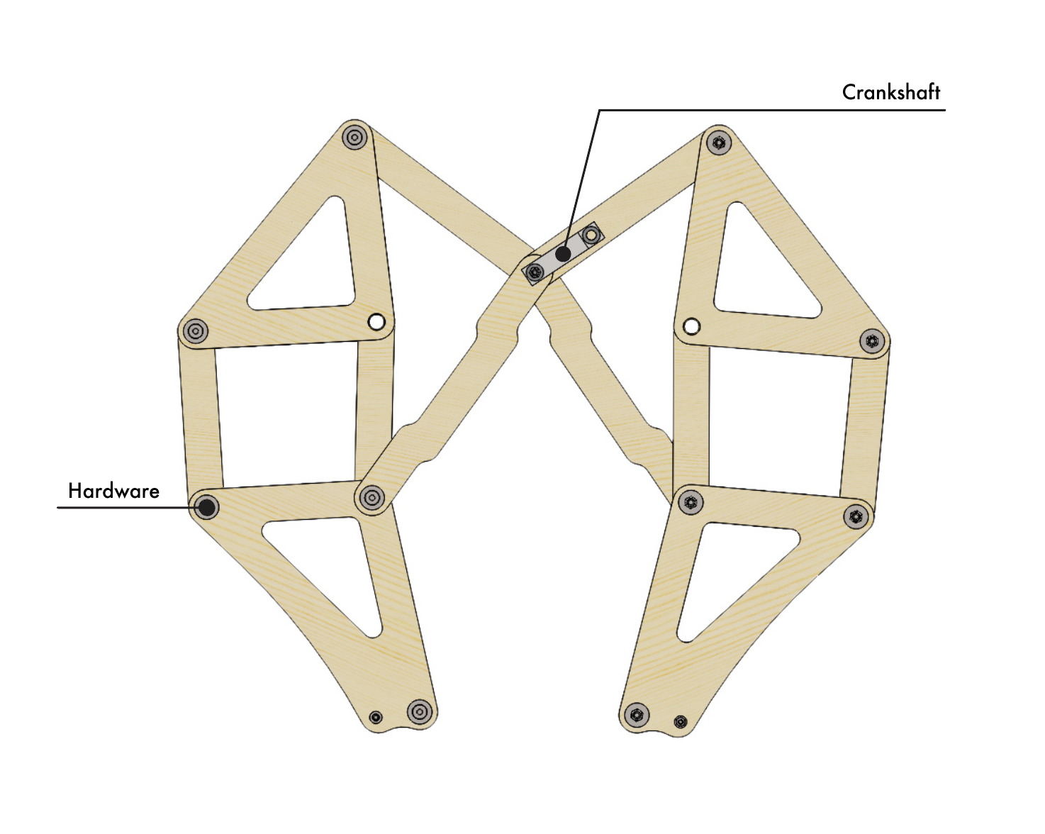
A) LEGS: Inspired by the Jansen Linkage
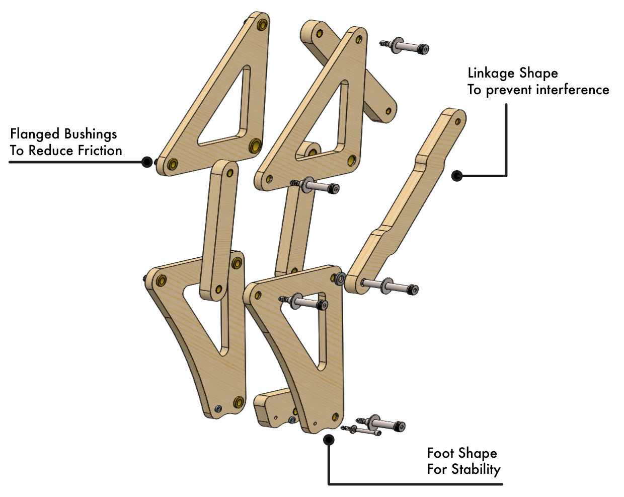
All of the components of the leg assembly were driven by the initial decision to use the Theo Jansen Linkage. Three full pairs of legs were used on either side of the machine to maximizie stability. Because leg linkages were made out of plywood, the leg hardware used was designed to ensure that there was never wood on wood contact.
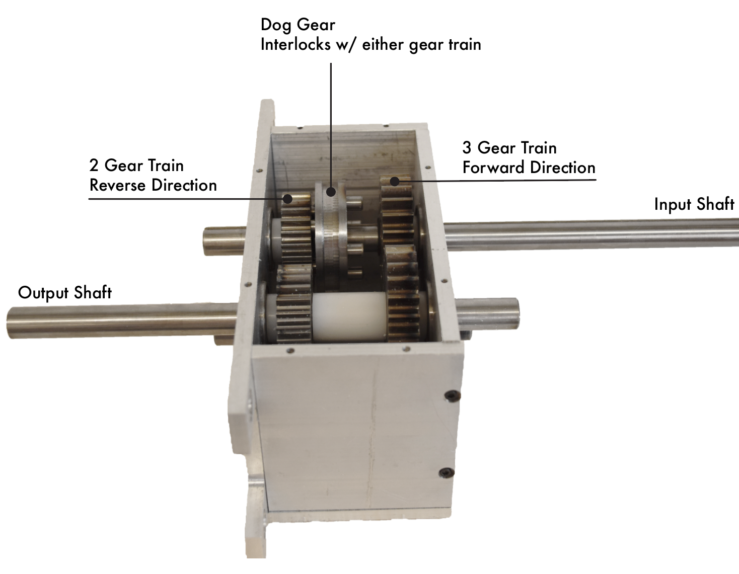
B) DRIVETRAIN: Pedal, Drive Shaft, Crank Shaft
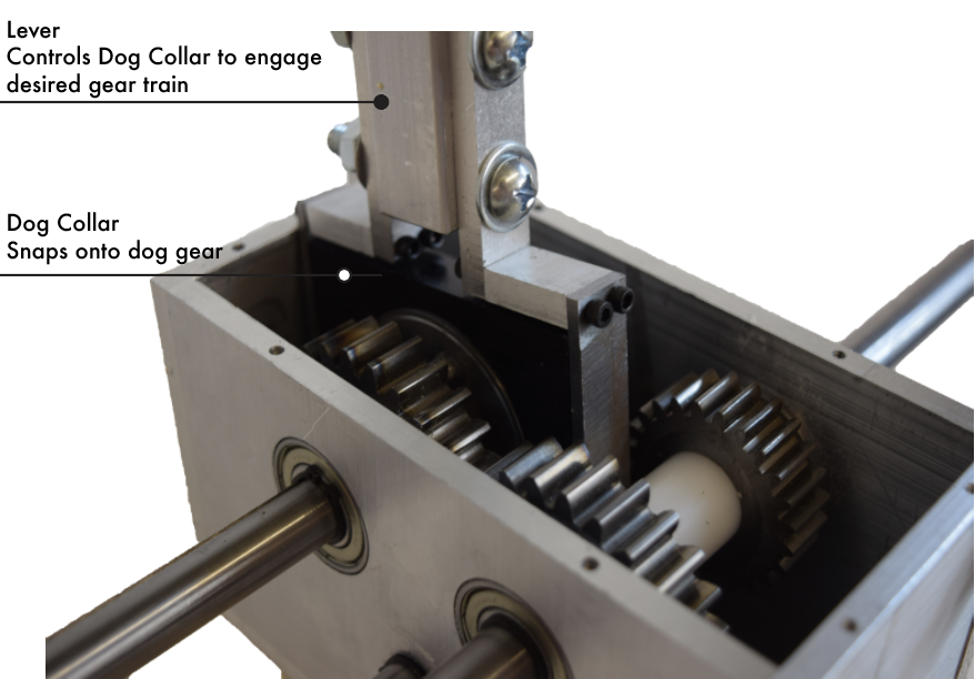
The biggest design component of the drive train was the transmission. Instead of employing a differential combined with a braking mechanism system, our group decided to design two transmissions with forward and reverse capabilities so that each half of the machine was controlled by a transmission and allowed for a zero-turn radius.
Drive Train Diagram
C) CHASSIS: Low-rider design
As one of the groups with the largest weight and height distribution, a huge goal of this machine was to remain stable regardless of the weight and height of the rider. Therefore, the group pursued a low-rider design with low center of gravity.
DESIGN PROCESS: We were given five weeks to design and develop our pedal-powered walking monster. This called for an incredibly fast-paced timeline in which there were fewer physical prototyping iterations and more 3D iterations in which designs were validated through Finite Element Analysis.
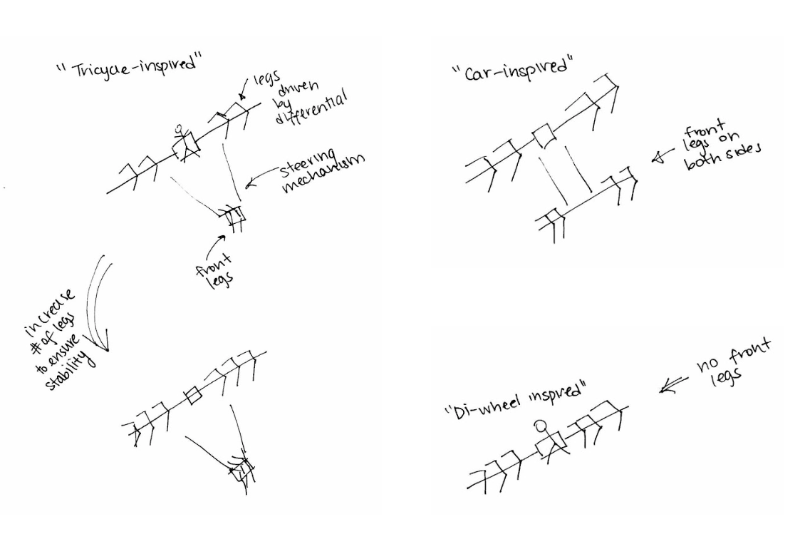
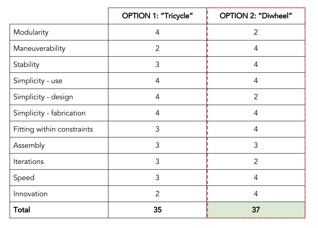
An initial brainstorm followed by research and ranking concepts against each other in a decision matric led to the selection of the machine's architecture.
Super quick sketches were made during the brainstorm to explore architecture concepts
This decision matrix was used to select between our top two architecture concepts
Our team split into three subteams: Legs, Drivetrain, and Chassis. As part of the drivetrain subteam, I co-designed and fabricated the transmission subassembly. Finite Element Analysis was used to calculate the worst case scenario stress and displacement in the keyway of the dog gear because failure of the key in the dog gear would disengage the drive train. The material and size of the dog gear was determined by iterating upon this calculation several times.
FEA was used in a similar manner in all the other subassemblies led by my teammates. While this was a mathematical approach, it allowed us to create a machine that theoretically would not fail under worst case scenarios.
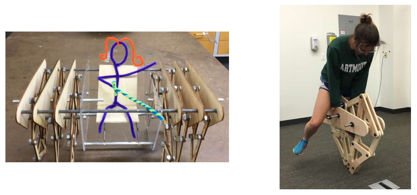
To ensure that the leg subassembly would work as modelled and calculated, we first made a scaled model of the basic architecture to test the linkage mechanism. We then fabricated one pair of to-size legs to test the deflection when the legs experienced load. These steps were crucial to making sure our final machine would function sucessfully.
Scaled model of basic architecture Testing deflection in one pair of to-size legs

